

Looking at house plans is almost second nature to some of us. I grew up with one grandfather who built houses, one who milled lumber for house, and a dad who owned a lumberyard supplying material to builders and DIY’ers. But this material can be like looking at hieroglyphics to some. When I found this article talking about house plans and how to better understand them I knew this was one I needed to link up on the Thomas Lumber Blog. I hope this helps some of you out there. Keep checking back on our blog for more helpful ideas, projects, and more.
If a floor plan’s myriad lines and arcs have you seeing spots, this easy-to-understand guide is right up your alley

The floor plan, or plan, is the most common of all architectural drawings. From builders to architects, Realtors to appraisers, everyone uses a floor plan. More than likely this is because the floor plan is the one drawing that tells us the most about a house. From the type of house to the size of the house, a floor plan reveals area, structure, circulation pattern, stair location, door and window locations, room layout and so much more.While floor plans do reveal a lot about the functional characteristics of a house, they often lack the information needed to describe the home’s overall feel. This is because they can’t easily show us what is going on in the third dimension. So when looking at a floor plan, remember that you’re looking at just one view of the house and you’ll need to look at other views to really understand all of the house’s features.Having said this, let’s look at what a floor plan shows.
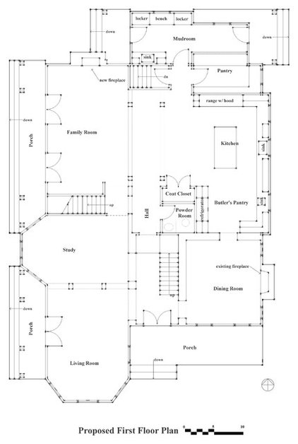
The overall floor plangives a flattened, two-dimensional bird’s-eye view of a floor level in the house. (Click this one to see an enlarged version.) Each room is shown, as are all the walls, doors, windows, stairs, walls, cabinets, appliances, plumbing fixtures and furniture.The rooms are labeled so we know where each functional area is in relationship to another room. And we’ll be able to see how we can get from room to room. Because windows and doors are shown, we can see how each relates to the others and to other items in a room. For example, we’ll be able to see if doors and windows are aligned to create view corridors.I find that the best way to understand a plan is to put yourself in it and “walk” around the home. As you take this virtual walk, record what you see, what you feel and how you get from room to room. Another way to understand the plan is to virtually put yourself in the middle of a room and record what you see as you look in at least four directions.
|
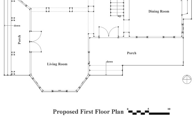
Every plan should include a legend that indicates what the project is and what floor the plan is of. The legend should also include the scale(1/4 inch equals 1 foot; 1/8 inch equals 1 foot etc.) at which the floor plan is drawn. Sometimes the scale can be written out, while other times a graphic scale, such as shown here, is provided. A graphic scale is useful when the drawing gets reduced or enlarged or otherwise altered so that putting a ruler on the plan to measure distances no longer helps.A legend can also include a north arrow. In fact, it’s a drawing convention that the top right of the drawing page is always north.Other items that can be included in a legend are the owners’ names, the project address, the architect and other designers’ names and the date (especially important with a construction drawing so revisions can be managed).
|
|
Wallshave to be the most important architectural element shown in any plan. Whether exterior or interior, walls are the elements that form the rooms and the overall house. Sometimes thin, as in a 2-by-4 wood-frame house, and sometimes thicker, as in a masonry house, walls should always be drawn to indicate this thickness.Walls are drawn as parallel lines with breaks where windows and doors occur. A particularly useful drawing convention that’s used in a remodeling or addition project is to show the existing walls with no fill between the parallel lines while showing the new walls with a pattern or dark color between the lines.
|
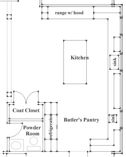
While an overall floor plan is commonly at a scale of 1/4 inch equals 1 foot, certain rooms are drawn at a larger scale — say, 1/2 inch equals 1 foot. This is the case with kitchens and bathrooms, as these rooms are often the most complex in a house. Cabinets, appliances, plumbing fixtures etc. can all be located and clearly shown in these larger-scale drawings.It’s often a good idea to have interior elevations drawn for these rooms. While we can see in the plan where the cabinets, appliances etc. are all located, we don’t know their height, type, or style. Only in an interior elevation will we see this information, because this drawing looks across straight at wall or other vertical surface.
|
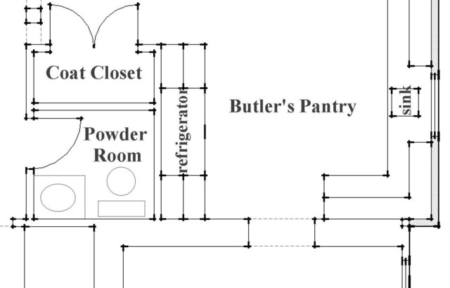
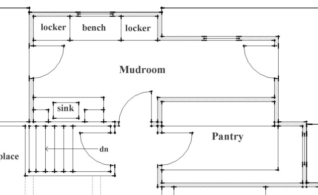
Doors and windowsare two of the most important elements shown on a floor plan. Each door and window is given a location and size. While windows are shown with three parallel lines in a wall, doors are typically shown as a straight line perpendicular to a wall and an arc that connects this line to the wall. The great thing about showing a door like this is we know which side has the hinges and which room the door opens into. For example, in this illustration the door leading into the pantry is hinged on the left (when you’re standing outside the pantry) and opens into the pantry.Note that for the mudroom, the two doors leading into the room are directly across from each other. This creates not only a strong circulation pattern but also a sight line that reinforces the pattern.
|
|
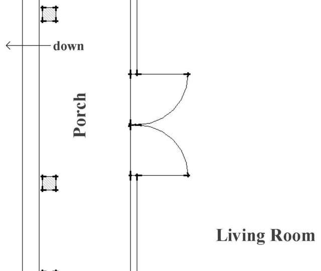
A French, or double, door is indicated by two arcs and lines, really as two single doors coming together. As with a single door, the direction of the door swing is indicated. In this case, the door swings into the living room, something that’s important to know when placing furniture in the room.
|
|
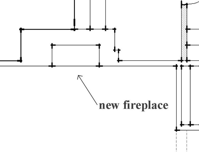
The fireplace is another architectural element shown in a floor plan. It is shown as an outer rectangle indicating the exterior wall of the fireplace or chimney and the inner rectangle indicating the firebox (the place where the fire actually burns).As with many such items, the plan will indicate the relationship between the fireplace and the other elements of the room. So the plan tells us if the fireplace is centered in the room, between windows or something else — all very important information. But it won’t provide any third-dimension information.
|
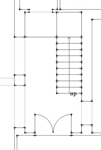
A stairwayis a very significant architectural element. Stairs take up a significant amount of floor space and have an effect on headroom, so accurately showing the stair in plan is very important. Drawn as a series of parallel lines, a staircase also has an arrow and a note indicating the direction of travel, either up or down.Modern building codes have a significant impact on the size and arrangement of stairs. From width to riser height to tread width and railing issues, no stair should be designed without a thorough understanding of these codes.
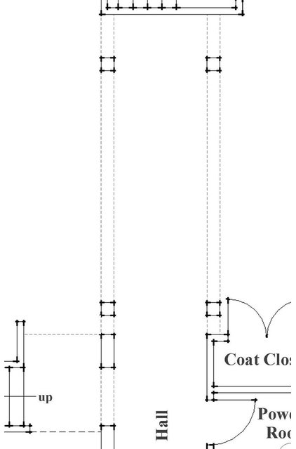
While ceiling transitions aren’t readily shown in a floor plan because they occur above, drawing conventions can reveal them. Dashed lines, as in the drawing here, allude to a change in the ceiling above the floor. We may not know what exactly this ceiling change is, but we know that there is a change, and we can then go to other drawings, such as a section(a vertical slice through the house instead of the horizontal slice that a floor plan is), to learn more.More: What You Can Learn From a Floor Plan